Contents
Index
DXF File to Strata Parcels
This option will read a file in an Autocad file in DXF format and generate parcels using
the DXF Polygons and Text Lot numbers.
It has been designed to generate the lots for all the floors in a unit title or strata development.
Read AutoCAD DXF File
Selecting the data
Open a blank job and select "Conversions/Autocad-DXF/Read DXF Strata Plan"
The following dialog box will appear:
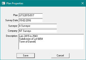
Enter the admin data for the plan (Plan Name, Date of Survey, Surveyor, Company, Plan Title).
When you hit the SAVE button the following Dialogue will appear:
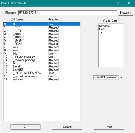
Set the Filename and select the layers which contain the lines for the parcel polygons
and the layer which has the lot number text strings.
In the example the Filename is UTS2015-017 and the text data for lot centroids
is on the fifteenth layer called "_LOT NUMBERS NEW".
The boundary lines for the parcels are on the following layers:
Layer 9 called "_bdy"
Layer 10 called "_eja unit boundary"
Layer 16 called "eja unit boundaries"
After you have selected the required layers, press the OK button and the selected layers will be displayed.
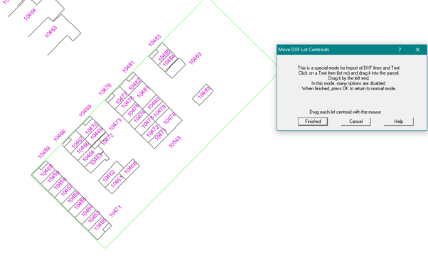
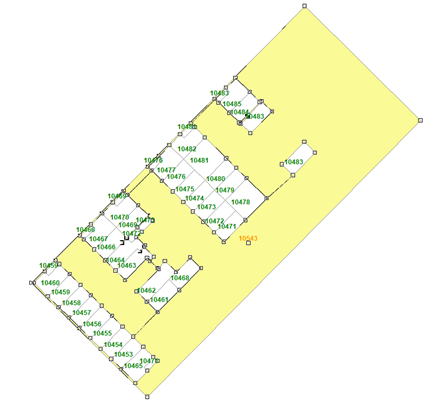
In this example, some of the parcels do not have the lot number centroid within the parcel boundaries,
and some of the lot numbers are shown on a diagram near to the data for a floor.
It is important that every polygon defining a parcel has its lot number inside the polygon surround.
For those lots where the lot number is outside the boundary, use the mouse to drag the reference point
for each lot number into the correct parcel.
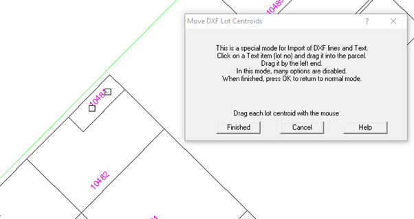
Note that zoom and pan can be used to assist this process
Delete any pieces of text which are not lot centroids for the parcels that you want to create.
When all parcel centroids have been checked, hit OK to generate the parcels.
In this view, the common property lot has been selected - note how it goes around all the included parcels.
The program will build the parcels by assembling the line segments around each lot number
Before it can do this, it will clean up the line segments from the drawing file.
There are three main operations:
- Snap together the end points of lines when they are close.
- Where the end point of a line abuts another line, split the line and snap to the new point.
- Where lines cross, create a new point where they cross and split both lines at that point.
As the parcels are being built it will fix the "parcel inside parcel" problem where it occurs.
This is very common for Common Property parcels as they are generally all that is left on a
floor after you take out the other parcels.
Finally, it will add connections to link any isolated parcels so that the whole floor can be managed as a group.
Completing the Floor and assembling the Job
As each floor is completed, use the expanding box to select all the parcels for the floor and unjoin them as a group.
A dialog box will then pop up and allow you to enter the floor level for that group.
We then have each floor complete and stored as an unjoined group.
The completed floors can then be appended to the job which has the boundary information.
After they have been appended, each floor can be selected using the parcel explorer and joined as a group.
UTS parcels can be edited in the usual way using the parcel editor.
If they are to be unjoined, it is best to unjoin and join a complete floor as a group.
During an adjustment, there is an option to include or exclude the ground floor lots.
After an adjustment has been completed, all the lots which have been excluded are moved
back to their correct relative position to the parcel surround.